

District heating implies direct supply of end customers, e.g. the supply of heat to single-family homes via district heating pipelines. You can find more general information about district heating in our blog post District heating FW 602.
The applications section will deal more specifically with testing process and the equipment technology required for this.
Pipeline network
Even though district heating networks are mainly located around the district heating source, the pipelines can have lengths in the range of several 10 km. Pipelines consist of the so-called medium pipes (pipes in direct contact with the heat transfer medium), which are thermally insulated to reduce energy losses along the supply network.
The medium pipes are always laid in pairs, as the district heating transport takes place in a circle: The heat is transported by means of a heat transfer medium from the source to the consumers in the “flow pipe”. From the consumer back to the source, the heat transfer medium is transported in the “return pipe”.
Medium pipes are made of different materials and insulated depending on the application, temperature of the heat transfer medium, design of the pipeline network and external conditions; plastic jacket composite pipes or steel jacket pipes are common.
Testing
To ensure long-term, safe and economic operation, newly laid district heating networks must be tested. With their AGFW FW 602 worksheet, the AGFW (Association of Energy Efficiency Companies for Heating, Cooling and CHP in Germany) has published its own set of rules for district heating pipes for testing medium pipes to prove tightness and strength. It describes and specifies the necessary test procedures to be carried out on newly constructed, extended and modified district heating pipelines.
Recommended procedures include, for example, overpressure test methods:
- Differential pressure measurement method
- Pressure measurement method, pressure measurement method simultaneous
- Hydrostatic test
The individual procedures differ in terms of device technology, implementation and procedure. In addition, there are specifications and regulations regarding the pipeline material; not every procedure may be used for a specific pipeline. The details of the procedures that can be carried out with the smart memo are explained below. In addition, advantages/disadvantages and differences in the device technology are highlighted.
Differential pressure measurement method
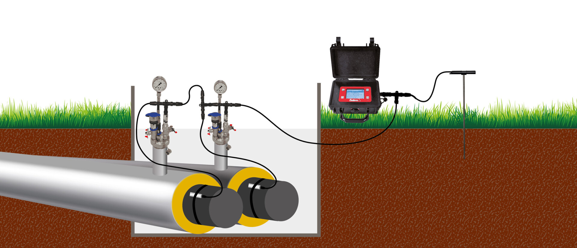
The differential pressure measurement method is an overpressure test with air. It is carried out on both pipelines, i.e. flow and return, at the same time. The analysis is carried out via the course of the differential pressure between them. The procedure is basically suitable for all materials, but is particularly recommended for PE pipelines. The procedure requires identical pipelines.
Procedure
The test is carried out with air, the materials of the flow and return must be identical. The test pressure is applied in both pipelines at the same time, i.e. the pipelines must be connected to each other. The hydraulic connection of both pipelines remains in place during the adjustment phase. In the following main test, both pipelines are separated from each other and the differential pressure between both pipelines is measured and recorded via the smart memo. The differential pressure is determined by calculating the difference between the two absolute pressure sensors. The evaluation of the differential pressure measurement procedure is carried out via the change in the differential pressure in the main test.
Advantages/Disadvantages
A change in the absolute pressure in a pipeline due to, for example, the characteristic, viscoelastic behaviour of a PE pipe is largely compensated for in this method, as both pipelines should behave similarly under the given conditions. Thus, the differential pressure measurement method is a suitable choice for PE pipelines, but also for metallic pipelines and where temperature fluctuations are to be expected, as these are also compensated for by the differential value formation.
With the smart memo, the differential pressure between flow and return is determined on the basis of two absolute pressure sensors (EDS2-P). This means that the absolute pressure in the individual pipelines is also always known. In addition to the result of the differential pressure measurement method, the smart memo carries out parallel tests according to the pressure measurement method and outputs evaluations for 3 tests at the end: differential pressure measurement method for flow and return, pressure measurement method flow and pressure measurement method return.
So if the test according to the differential pressure measurement method fails, e.g. because one of the two pipelines is leaking, the results of the pressure measurement method can be used to reliably determine in which pipeline there is a leak.
Since characteristic, viscoelastic processes of both pipes are compensated via the differential pressure formation, the data of both pipelines must be identical, i.e. the possibility of applying the method for different pipelines is not possible.
Required measuring devices and equipment
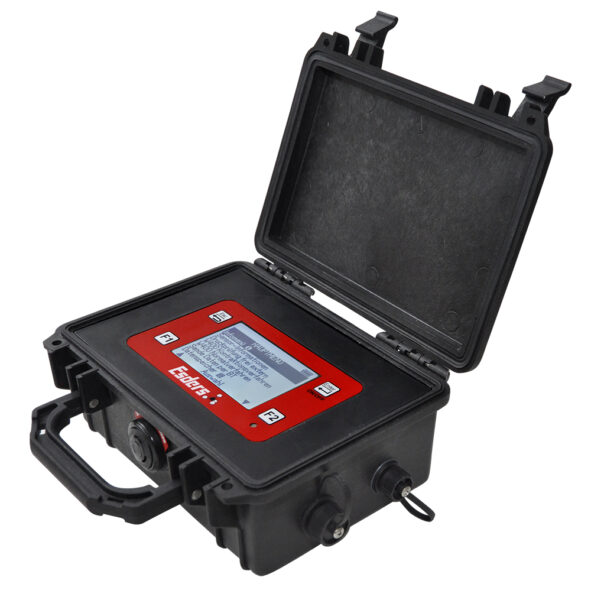
A smart memo with activated Option AGFW FW 602 is required to perform this test. The smart memo guides you through the test in an automated process, displays measurement data and progressions, and stores and documents all relevant test data.
Sensors required:
– EDS2-P absolute pressure sensor, which is connected either to a single pipeline or to a composite line of both pipelines.
– Contact temperature sensor EDS2-T, which is also connected to a single pipeline or to a network of pipelines.
Optionally, the EDS2-T ground stake can be used as a temperature sensor, which additionally detects the ground temperature, if required. All sensors used must receive initial certification in a DAkkS-accredited testing laboratory.
To connect to smart memo, one B11 connection cable is required for each sensor. To connect several sensors to the smart memo, one T-connector B11 must be used for each additional sensor. Since in most cases there is only a short distance between the pressure sensor and the contact sensor, we recommend a 1 m connection cable B11. For all other connections, we recommend the B11 5-metre connection cable.
Optionally, a ” 3-sided claw ” adapter with ball valve can be used, if both pipelines are to be tested as one unit. On the inlet side, a suitable compressor can be connected via a claw coupling; on the outlet side, the two pipelines (flow/return) are connected via hose NBR13. After the pressure build-up phase, the ball valve on the T-piece can be closed.
A suitable test element, e.g. the test head HEINZ, is required on both pipelines. The pressure hoses can be connected to the test head, pipelines can be closed via the ball valve and the pressure sensors and pressure gauge can be connected.
- 1x smart memo ( Article 221200)
- 1x Option AGFW FW 602 ( Article 222627)
- 2x EDS2-P 10 bar 0,1% 0-40 °C DAkkS ( Article 361000)
- 2x Temperature sensor contact element EDS2-T 0,1K DAkkS ( Article 222206)
- 1x Temperature sensor ground stake EDS2-T 0,1K DAkkS ( Article 222207) optional
- 3x Connecting cable B11 5 m ( Article 227002)
- 2x Connecting cable B11 1 m ( Article 227220)
- 4x T-piece B11 ( Article 227006)
- 2x Test head HEINZ ( Article 402002)
- 2x Pressure gauge 10bar ( Article 402074)
- 1x Adapter 3-sided claw ( Article 402057)
- 2x Hose NBR 3m ( Article 225131)
Pressure measurement method
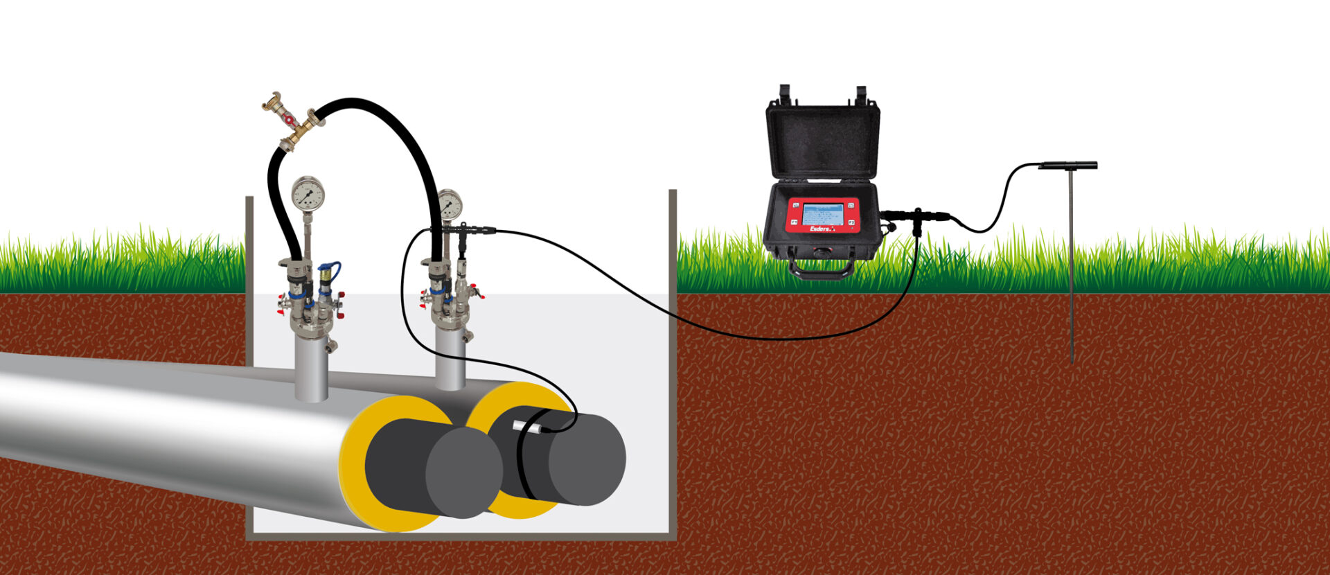
The pressure measurement method is a test with positive air pressure, where only a single pressure sensor is required. The test is evaluated by the change of absolute pressure during the test phase. With the pressure measurement method, an integral test of test sections is carried out, i.e. flow and return pipes can also be tested together with this method, provided that they are hydraulically connected to each other. This method is not suitable for PE pipelines or conditions with large temperature fluctuations. If both pipelines (flow and return) are to be tested as a composite, they may have different pipe data (diameter, length, etc.).
Procedure
The test is carried out with air. The test can either be carried out for only one pipeline (flow or return) or both pipelines (flow and return) can be tested together as a connected pipeline. Since in this case the pipelines are considered as a compound with a total volume (individual volumes are simply added up), a pressure sensor and a contact sensor are sufficient to test the entire pipeline. The hydraulic connection of both pipelines (via a suitable hose) remains during the test.
After the test pressure has been applied to the individual pipeline or the entire pipeline, an adjustment time (temperature adjustment) follows, the duration of which depends on the total volume. In the following main test, the absolute pressure in the test pipeline is measured and recorded via the smart memo. The evaluation of the pressure measurement procedure is carried out via the change in absolute pressure during the main test.
Advantages/Disadvantages
Pressure changes due to temperature fluctuations and due to characteristic, viscoelastic processes in a PE pipe can influence the result in this procedure. Therefore, this method is not recommended for PE pipelines. This method must also be viewed with caution in conditions where large temperature fluctuations are to be expected. These can have a negative effect on the result of the test. If a leak is detected in a connected test pipeline using this method, the location of the leak (flow or return) cannot be identified. Here, the differential pressure measurement method has advantages because two absolute pressure sensors are used and in this way the leakage pipe can be detected. If both pipes (flow and return) are to be tested as a composite, they may have different pipe data (diameter, length, etc.), i.e. this method can be used for different pipes. A small set of measuring equipment is needed to implement the pressure measurement method, as both pipe networks (as a unit) can be tested with only one absolute pressure sensor and one contact sensor.
Required measuring devices and equipment
A smart memo with activated Option AGFW FW 602 is required to perform this test. The smart memo guides you through the test in an automated process, displays measurement data and progressions, and stores and documents all relevant test data.
Sensors required:
– two EDS2-P absolute pressure sensors, one of which is connected to the supply pipeline and the other to the return pipeline.
– Two temperature sensors in the form of EDS2-T contact probes, of which one is connected to the supply pipeline and the other to the return pipeline.
Optionally, the EDS2-T temperature sensor can be used as a ground stake, which additionally detects the temperature during grounding if required.
All sensors used must receive initial certification in a DAkkS-accredited testing laboratory.
To connect to smart memo, one B11 connection cable is required for each sensor. To connect several sensors to the smart memo, one T-connector B11 must be used for each additional sensor. Since in most cases there is only a short distance between the pressure sensor and the contact sensor, we recommend recommend a 1 m connection cable B11. For all other connections, we recommend the B11 5-metre connection cable.
Optionally, the adapter 3-sided claw with ball valve can be used if both pipelines are to be tested as a compound. On the inlet side, a suitable compressor can be connected via a claw coupling; on the outlet side, the two pipelines (flow/return) are connected via hose NBR13. After the pressure build-up phase, the ball valve on the T-piece can be closed.
A suitable test element, e.g. the test head HEINZ, is required on both pipelines. The pressure hoses can be connected to the test head, pipelines can be closed via the ball valve and the pressure sensors and pressure gauge can be connected.
- 1x smart memo ( Article 221200)
- 1x Option AGFW FW 602 ( Article 222627)
- 1x EDS2-P 10 bar 0,1% 0-40 °C DAkkS ( Article 361000)
- 1x Temperature sensor contact element EDS2-T 0,1K DAkkS ( Article 222206)
- 1x Temperature sensor ground stake EDS2-T 0,1K DAkkS ( Article 222207) optional
- 2x Connecting cable B11 5 m ( Article 227002)
- 1x Connecting cable B11 1 m ( Article 227220)
- 2x T-piece B11 ( Article 227006)
- 2x Test head HEINZ ( Article 402002)
- 2x Pressure gauge 10bar ( Article 402074)
- 1x Adapter 3-sided claw ( Article 402057)
- 2x Hose NBR 3m ( Article 225131)
Simultaneous pressure measurement method
As an alternative to the pressure measurement method, the smart memo offers the “simultaneous pressure measurement method”, which uses two absolute pressure sensors to simultaneously perform a pressure measurement in the flow pipeline and a pressure measurement in the return pipeline. The test is evaluated by the absolute pressure value during the test phase. The total test duration is thus the same as for the pressure measurement method, but at the end of the test, the simultaneous execution has the advantage that a possible leak can be reliably identified. This method is not recommended for PE pipelines and the results must therefore be interpreted with caution when the temperature fluctuates. Since an independent test is carried out on both pipelines with separate sensors, the pipe data can be different, i.e. this procedure can be used for different pipelines. The parallel execution with the smart memo effectively saves time.
Procedure
The test is carried out with air in parallel on two pipelines (flow and return), i.e. each pipeline must be equipped with an absolute pressure sensor and a contact sensor. The pressure build-up to the test pressure is carried out together, i.e. the pipes must be hydraulically connected for this. After the pressure build-up, both pipelines are disconnected so that an independent test runs in each line. Then an adjustment phase takes place in each pipeline. In the following main test, the absolute pressure in each test pipeline is measured and recorded via the smart memo. The evaluation of the pressure measurement procedure is carried out via the change in absolute pressure during the main test. Finally, two independent evaluations with results are output for the supply and for the return pipeline.
Advantages/Disadvantages
Pressure changes due to temperature fluctuations and due to characteristic, viscoelastic processes in a PE pipe can influence the result in this procedure. Therefore, this method is not recommended for PE pipes. This method must also be considered with caution in conditions where large temperature fluctuations are to be expected. These can have a negative effect on the result of the test.
This procedure can be used to clearly identify a leak. Since two independent tests are carried out in parallel, the pipelines can have different pipe data (diameter, length, etc.), i.e. this procedure can be used for different pipes.
Due to the parallel execution, the test time is halved compared to the “normal” pressure measurement method on two individual pipelines.
Required measuring technology and equipment
A smart memo with activated Option AGFW FW 602 is required to perform this test. The smart memo guides you through the test in an automated process, displays measurement data and progressions, and stores and documents all relevant test data.
Sensors required:
– two EDS2-P absolute pressure sensors, one of which is connected to the supply pipeline and the other to the return pipeline.
– Two temperature sensors in the form of EDS2-T contact probes, of which one is connected to the supply pipeline and the other to the return pipeline.
Optionally, the EDS2-T temperature sensor can be used as a ground stake, which additionally detects the temperature during grounding if required.
All sensors used must receive initial certification in a DAkkS-accredited testing laboratory.
To connect to smart memo, one B11 connection cable is required for each sensor. To connect several sensors to the smart memo, one T-connector B11 must be used for each additional sensor. Since in most cases there is only a short distance between the pressure sensor and the contact sensor, we recommend recommend a 1 m connection cable B11. For all other connections, we recommend the B11 5-metre connection cable.
Adapter ” 3-sided claw “ is used to hydraulically connect the supply pipeline and the return pipeline when building up pressure together. On the inlet side, a suitable compressor can be connected via a claw coupling; on the outlet side, the two pipelines (flow/return) are connected via hose NBR13. After the pressure build-up phase, the ball valve on the T-piece can be closed.
A suitable test element, e.g. the test head HEINZ, is required on both pipelines. The pressure hoses can be connected to the test head, pipelines can be closed via the ball valve and the pressure sensors and pressure gauge can be connected.
- 1x smart memo ( Article 221200)
- 1x Option AGFW FW 602 ( Article 222627)
- 1x EDS2-P 10 bar 0,1% 0-40 °C DAkkS ( Article 361000)
- 1x Temperature sensor contact element EDS2-T 0,1K DAkkS ( Article 222206)
- 1x Temperature sensor ground stake EDS2-T 0,1K DAkkS ( Article 222207) optional
- 3x Connecting cable B11 5 m ( Article 227002)
- 2x Connecting cable B11 1 m ( Article 227220)
- 4x T-piece B11 ( Article 227006)
- 2x Test head HEINZ ( Article 402002)
- 2x Pressure gauge 10bar ( Article 402074)
- 1x Adapter 3-sided claw ( Article 402057)
- 2x Hose NBR 3m ( Article 225131)
Hydrostatic test
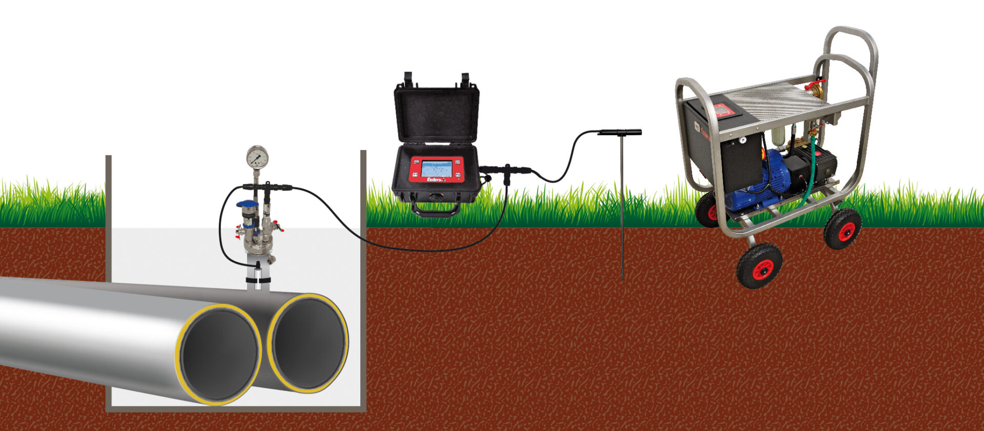
Some pipelines require a test with water pressure. The water pressure test is used to test the tightness and strength against internal pressure of preassembled pipeline sections or test sections. The test is performed with a single pressure sensor and can be performed for several contiguous or interconnected sections of a total pipeline system. The test procedure includes two periods of holding time at the selected test pressure with an intermediate pressure reduction. The pressure drop in the second holding period is decisive for the evaluation of the test.
Procedure
The test is carried out with water. An absolute pressure sensor and a contact sensor are required to carry out the test. After filling and venting, wait until the temperatures of the water and the pipeline system have equalised. The test in the smart memo starts with the pressure build-up to the selected test pressure. As soon as the test pressure is reached, a 1st holding phase without pressure maintenance follows for 90 minutes. After this phase, the pressure is reduced to 2 bar and a subsequent settling phase of 30 minutes follows. Finally, the pressure must be built up again to the test pressure, followed by a 2nd holding phase as the main test.
During the main test (2nd holding phase), the absolute pressure in the test pipeline is measured and recorded by the smart memo. The test is evaluated via the pressure drop during the main test, which must not exceed 100 mbar.
Required measuring devices and equipment
A smart memo with activated option AGFW FW 602 is required to perform this test. The smart memo guides you through the test in an automated process, displays measurement data and progressions, and stores and documents all relevant test data.
Sensors required:
– EDS2-P absolute pressure sensor with sufficient measuring range and DAkkS initial certification
– temperature sensor as a contact sensor EDS2-T.
Optionally, the EDS2-T temperature sensor can be used as a ground stake, which additionally detects the temperature during grounding if required.
All sensors used must receive initial certification in a DAkkS-accredited testing laboratory.
To connect to smart memo, one B11 connection cable is required for each sensor. To connect several sensors to the smart memo, one T-connector B11 must be used for each additional sensor. Since in most cases there is only a short distance between the pressure sensor and the contact sensor, we recommend recommend a 1 m connection cable B11. For all other connections, we recommend the B11 5-metre connection cable.
A suitable test element, e.g. the test head HEINZ, is required on the pipeline. The pressure hose from the motor test pump can be connected to the test body, pipelines can be closed via the ball valve and the pressure sensors and control manometers can be connected. A motor test pump, e.g. the MPP 30-30, is required to generate the test pressure. A pressure hose with a suitable internal diameter and connections between the motor test pump and the test head is also required.
- 1x smart memo (Article 221200)
- 1x Option AGFW FW 602 ( Article 222627)
- 1x EDS2-P 25 bar 0,1% DAkkS ( Article 361017)
- 1x Temperature sensor contact element EDS2-T 0,1K DAkkS ( Article 222206)
- 1x Temperature sensor ground stake EDS2-T 0,1K ( Article 222207) optional
- 2x Connecting cable B11 5 m ( Article 227002)
- 1x Connecting cable B11 1 m ( Article 227220)
- 2x T-piece B11 ( Article 227006)
- 1x Test head HEINZ ( Article 402002)
- 1x Pressure gauge 25 bar ( Article 402050)
- 1x Test pump MPP 30-30 (Artikel 401005)
- 1x Pressure hose Hyd16 DN 16 10 m (Artikel 402011)