In our blog post on the subject of serviceability, we also cover the functional testing of gas pressure regulators (GPR). In our previous article, we looked at the theoretical background, presented and explained the relevant regulations. This article, will now cover the practical implementation of the functional test.

Before starting the test, a suitable connection to the installation must be selected – similar to the serviceability test. There are various options here, which must be checked on site or in advance. If necessary, the specialist company carrying out the work also has corresponding work instructions that specify the points at which the connection to the gas installation must be made. Suitable connection points can be, for example, measuring openings in/on the GPR or test openings built into the pipe system. These can be used with suitable adapters and seals. In any case, it is recommended to choose a connection as close as possible to or on the GPR. This avoids undesirable impacts caused by parts of the line that are included in the test. For more information on test & measurement openings in gas installations, we have a short blog post here. In this article, we describe the test via the meter connection with the GasTest delta3.

Output and closing pressure

Once the meter is connected, the first thing that is usually measured is the outlet pressure (sometimes also called flow pressure). To do this, the gas must be taken off so that it comes into motion in the pipe. However, the question arises as to how a suitable volume flow can be set that corresponds to a real decrease. From our point of view, there are several possibilities in practice. The most reliable and at the same time most informative variant is to use the “ pipe cleaning function ” on the gas boiler. This puts the system into a kind of test mode and a gas acceptance test is carried out by the gas boiler.

However, some inspectors do not want to or are not allowed to use this option due to operational instructions, as it means interfering with the customer’s installation.

Unlike the GPR, the gas boiler belongs to the owner and not to the network operator. For these cases, a measuring device such as the GasTest delta3 is ideal, with which a fully or partially automated functional test of the GPR can be carried out. For this purpose, the pump built into the device is used together with the gas bladder housed in the device’s case. In this case, the gas extraction produced is less than when using the chimney sweep function of the gas boiler.

A third possibility is to use a hand pressure ball with a regulating valve, which is connected to the gas installation and the meter via a corresponding Y-hose. Gas is released into the room in a controlled manner via the open fine adjustment valve and in this way a gas flow is created in the pipe.

However, we cannot recommend this variant as there is an increased safety risk due to escaping gas (see DGUV Rule 100-500, chapter 2.31). In addition, this variant will no longer be allowed in the future due to the expected requirements from the EU methane regulation (ban on the release of unburned natural gas).

In all cases, the measured outlet pressure must be within the control group of the GPR. This is indicated on the nameplate of the controller under AC ( Accuracy Class ) and is usually 10%. Together with the specification pds (pressure downstream = outlet pressure), which is usually 23 mbar, the permissible tolerance range for the outlet pressure can be determined, i.e. in this specific case 23 mbar +/- 10% = 20.7 – 25.3 mbar.

After measuring the outlet pressure, the closing pressure (sometimes also called the resting pressure) is measured. For this purpose, the previously started gas sampling is stopped and the pressure is observed. Once the value is stable, it can be saved. According to DVGW G 495, stable means that the pressure increase must not exceed 1 mbar within three minutes. Otherwise, an increase in pressure is considered a defect that must be rectified. In practice, shorter observation periods are often used. Here, the specialist or the expert on site must decide which times should be observed as a minimum for evaluating the stability. In addition, the closing pressure must be within the closing pressure group of the GPR. This can also be found on the type plate under SG and is usually 20%. The permissible tolerance range for the closing pressure would therefore be 23 mbar +/- 20% = 18.4 – 27.6 mbar.

Almost simultaneously with the closing pressure, the tight closure of the GPR can be checked and stored in the device. In addition to the visual, external check of the GPR (inspection), it is sufficient to observe the closing pressure. If it is stable (see above), it can be assumed that the GPR is tight.

Medium pressure regulators with SSV

Typenschild eines Gasdruckreglers

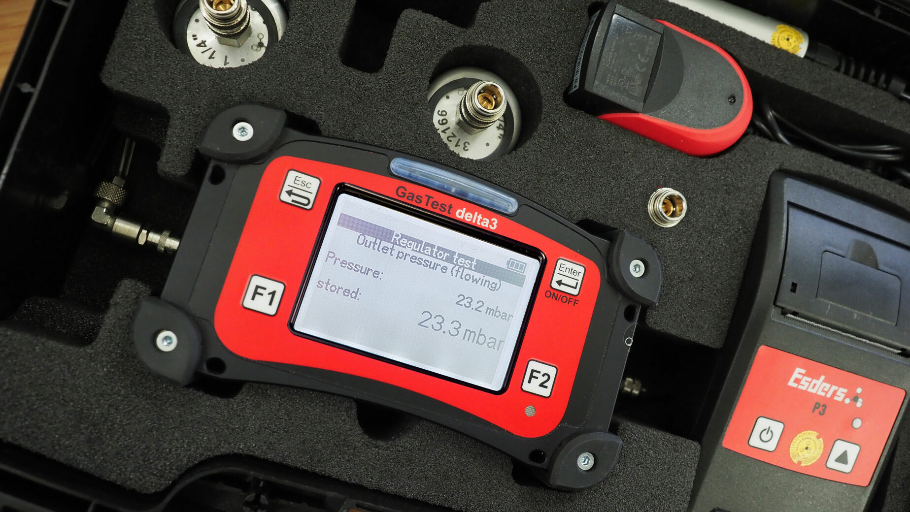
For low-pressure regulators, this concludes the functional test. In the case of medium-pressure regulators, safety devices are prescribed due to the increased hazard potential, and these must also be tested as part of the functional test.

In practice, in most cases a safety shut-off valve (SSV) is used. In the event of an impermissibly high pressure (e.g. due to failure of the GPR) in the downstream pipeline system, this valve ensures that the gas supply is cut off, so that the pipeline system, the gas meter, the gas boiler, etc. are not damaged by the higher upstream pressure (mains pressure).

In normal operation, the valve is open. Optionally, a gas shortage safety device (GMS – from German Gasmangelsicherung), a gas flow monitor (GS – from German Gasströmungswächter) and/or a safety relief valve (SBV – from German Sicherheitsabblaseventil) for leakage gas quantities are installed at or together with some GPRs. However, we do not want to go into this in more detail here, but concentrate on the SSV.

With the SSV, the upper set pressure and slab tightness are usually tested. This requires a controlled pressure increase in the downstream piping system to test the upper response pressure or shut-off point of the SSV.

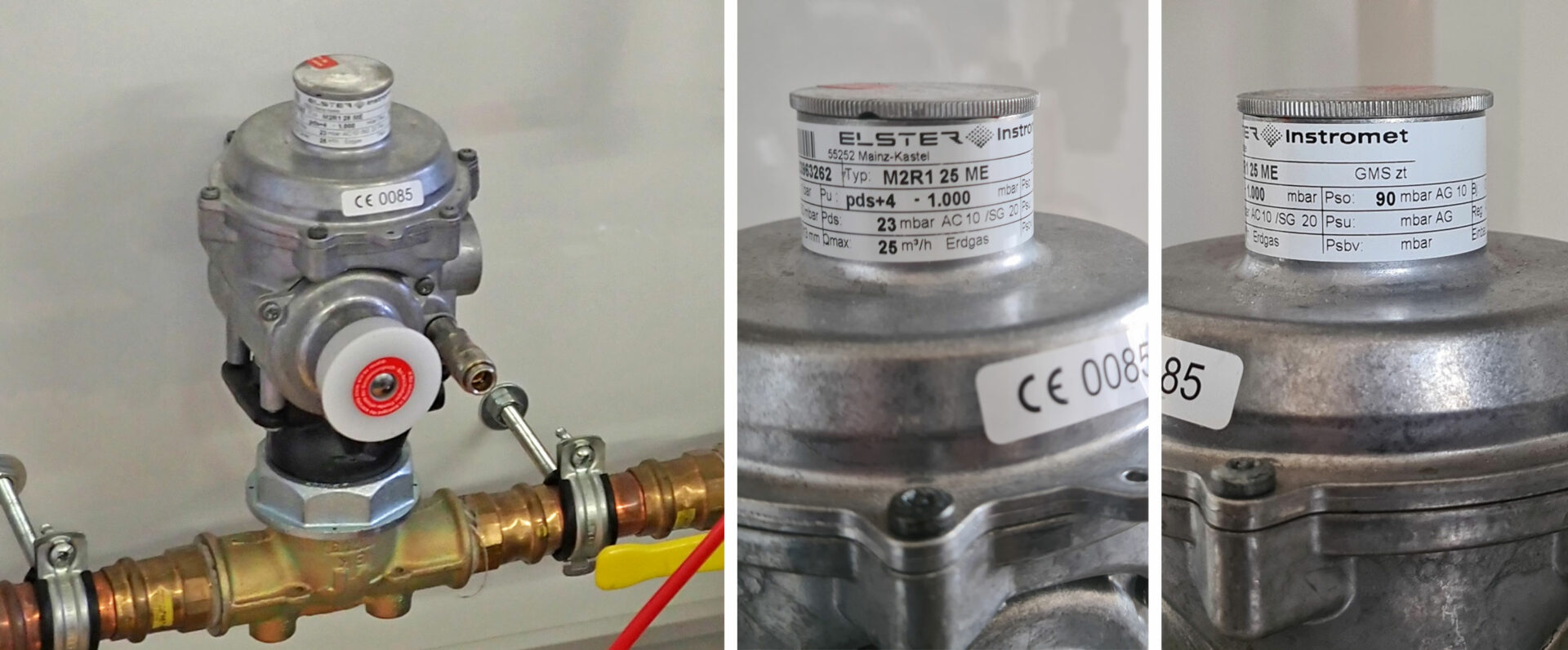
For the switch-off point, a response group (AG – from German Abschaltpunkt) applies, which indicates the percentage permissible deviation from the response pressure. The corresponding information can also be found on the type plate of the GPR. Under the abbreviation pso (Druck SAV „Oben“ = Pressure SSV “Top”) you will find the upper response pressure that leads to the closing of the SSV and thus to the disconnection of the gas supply and under AG (Ansprechgruppe = response group) the permissible deviation for this.

The values for the upper response pressure can vary depending on the GPR and are usually between 60 and 100 mbar. A tolerance of +/- 10% usually applies to the AG.

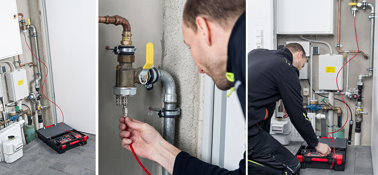
There are again various possibilities for putting pressure on the downstream system. However, it is important to ensure that components that cannot withstand the increased pressure are not exposed to it. In addition, the volume to be pressed on should be kept as small as possible so that pipe parts that are not to be tested are not included. Before the test, you should think about a suitable connection to the GPR and, if necessary, briefly dismantle components (e.g. gas meters) or exclude downstream parts of the pipeline system from the test by using appropriate seals (e.g. meter seal for single-pipe regulators).

The chimney sweep function cannot be used at this point because this only allows gas to be taken off, but not the pipe to be pushed open.

The use of a hand pressure ball is also not recommended, as this forces air into the pipe system, which can lead to a malfunction of the gas boiler. It is also very difficult to increase the pressure in a controlled way in this way.

We therefore recommend the variant mentioned above with the pump built into the meter. The advantage of this variant is the controlled gas pressure in the pipeline. This gas is taken from the system beforehand. It is therefore also important that the main shut-off device (HAE – from German Hauptabsperreinrichtung) remains open during the entire test. Moreover, in this way no gas, either unburned or burned, is released into the atmosphere or flared, but is temporarily stored in the gas bladder integrated in the case. This is the preferred method according to the EU methane regulation.

After the SSV has “triggered”, i.e. the valve has shut off further gas supply, the set pressure or shut-off point has thus been reached and stored, the tight shut-off of the SSV (sometimes also called zero shut-off) must still be checked.

The upper response pressure of the SSV can be tested beforehand up to three times in succession, as desired, and the results can be documented in the device. To test the tight seal of the SSV, the pressure must then be released again and the pipeline depressurised. It is also possible to do this with a pump built into the measuring device, which prevents gas escaping and ensures the safety of the process.

After the pressure has been released, it is observed and checked to see if it is stable. According to the regulations, this is repeated if no pressure increase has been detected within three minutes or if it has increased by a maximum of 1 mbar. If there is a larger pressure increase, the SSV is considered to be leaking. This represents a defect that must be remedied. After all tests have been carried out successfully, the SSV must be unlocked again and the normal condition of the system restored.

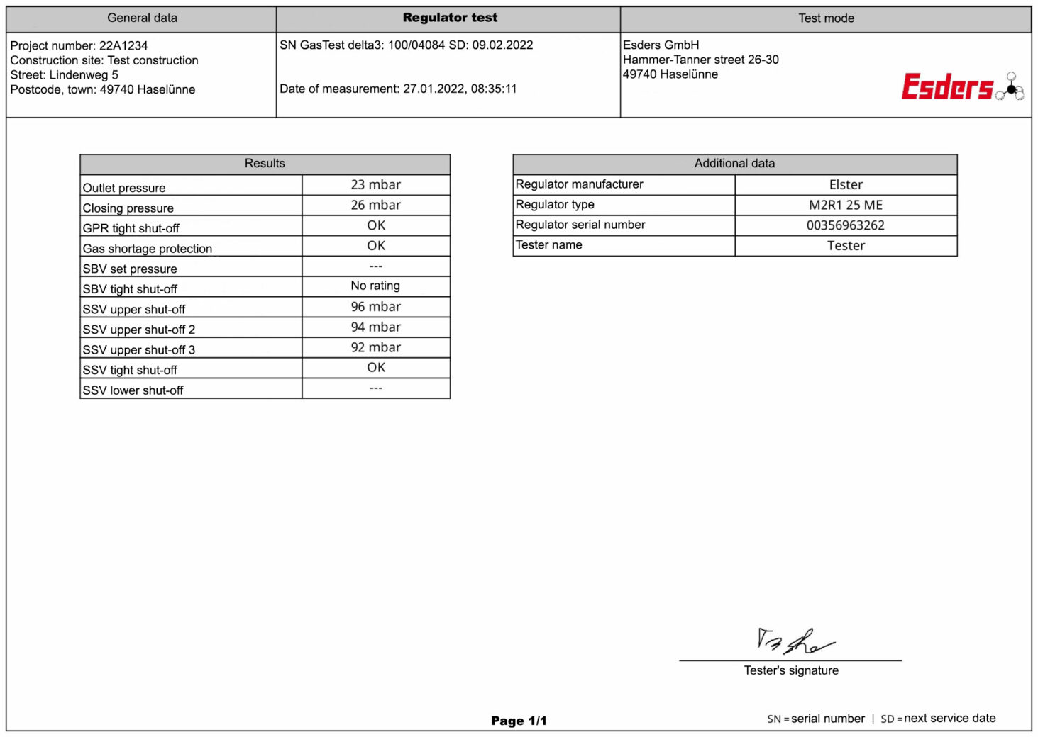
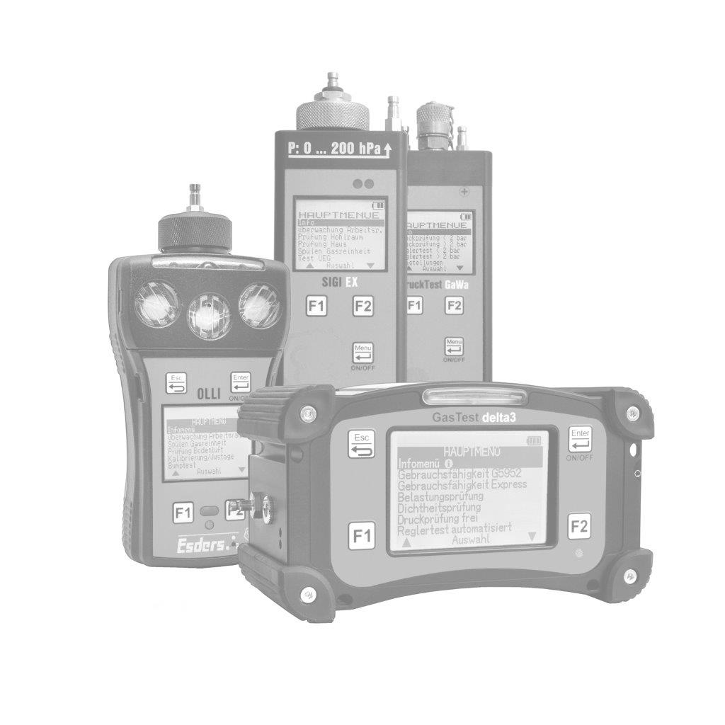
All recorded values must be documented at the end in the relevant test report, together with specific key GPR data (e.g. model, serial number, etc.) GasTest delta3, combined with our Esders Connect App and associated online portal, offers a wide range of options for this task.

Device technology and equipment

Article

Charging & Carrying Equipment

  • 202002 Power Supply 230 V
  • 202003 Car adapter cable 12 V
  • 212107 Case with balloon and charger

Connection Accessories

  • 312028 Adapter test coupling S21K – 1/8“
  • 312030 Adapter test coupling S21K – 1/8“ angled
  • 312100 Test plug conic ½“ with ball valve
  • 312101 Test plug conic ¾“ with ball valve
  • 312102 Test plug conic 1“ with ball valve
  • 312018 Test cap DN 25 (for single-pipe meter)
  • 312025 Test cap DN 40 (for single-pipe meter)
  • 312166 Adapter screw connector 1 ¼“ (for 2-pipe gas meter)
  • 312167 Adapter screw connector 1 ¾“ (for 2-pipe gas meter)
  • 312168 Adapter screw connector 2“ (for 2-pipe gas meter)
  • 212021 pressure resistant Y-connection (for 2-pipe gas meter)
  • 312089 Connection hose

Charging & carrying equipment

Connection accessories