

Table of Contents
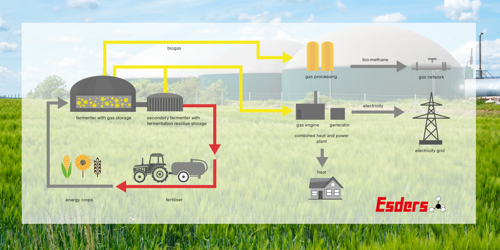
From the previous blog posts on the topic of biogas, we have learned that biogas, just like solar, hydro and wind energy, is one of the renewable energy sources. In addition to renewable raw materials such as maize and grain, waste from private households, biowaste from agriculture, manure and slurry from animal husbandry as well as food leftovers and other biodegradable waste from companies or the private sector are biodegraded as so-called substrates in an anaerobic environment (without oxygen) by bacteria, which produces energy. Energy as a generic term, because electricity and heat can be generated through combustion in the CHP unit or, through appropriate gas processing, it can be fed into the natural gas grid. In addition, the resulting fermentation substrate can also be used as fertiliser in agriculture. The methane content depends on the substrate composition. Depending on this, it varies between 50 and 75 percent. The higher the proportion of methane, the more suitable the biogas is for efficient heat and power generation. Conventional natural gas is a fossil energy source that is not available in unlimited quantities.
Structure biogas plant
Efficiency of a biogas plant
The decisive factor for the efficiency of a biogas plant is not only the substrate composition in order to generate as much methane as possible for energy production. A biogas plant must be gas-tight. Scientists assume that methane is about 25 times more potent than carbon dioxide. Thus, even small amounts provide a large greenhouse effect. The second negative effect of a leak at a biogas plant describes the financial consequences. If gas flows unhindered into the atmosphere, it can no longer be converted into energy.
The following graph shows an example of the monetary loss caused by the escape of a certain gas concentration at the vent:
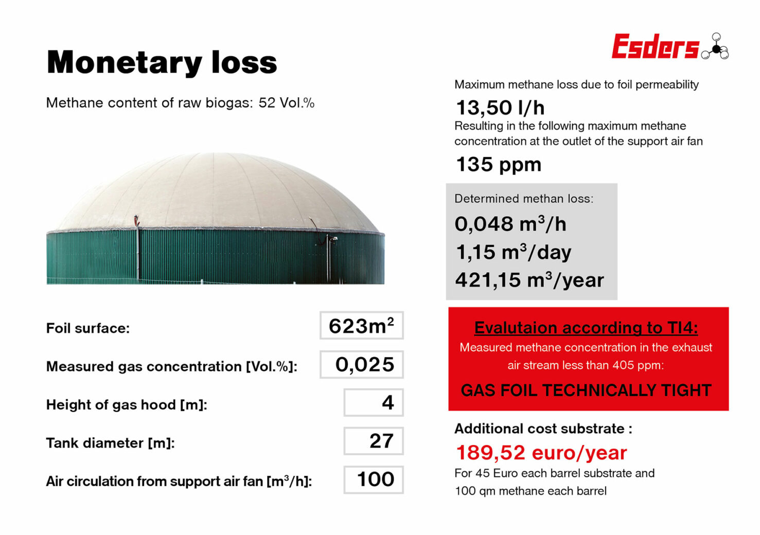
This graph shows the monetary loss with a tight gas foil, where the nevertheless very low gas concentration of 250 ppm, measured in the exhaust air flow of the container, diffuses through the lower foil of the supporting air roof. If a calculation were made of the additional costs of the substrate due to a tear in the foil, the costs would be much higher.
German Technical Rule for Plant Safety 120 – Biogas
TRAS 120 is a set of technical regulations that addresses the safety requirements for biogas plants. TRAS120 states, among other things (excerpt):
- that the tightness of membrane systems shall be monitored. Installations with such a membrane system shall be operated with an outer casing to ensure continuous monitoring of this interstitial space. If the membrane system is a single-shell system, it must be checked daily for mechanical damage, at least weekly for leaks at locations such as the vessel connection and inspection openings of the membrane by means of transportable gas detection equipment, and at least every six months by means of methane-sensitive optical methods.
- A test for leaks by means of a suitable, methane-sensitive, optical method shall be carried out after the expiry of three years between each leakage test.
- The space between the gas membrane and its outer casing shall be monitored in accordance with Chapter 3.5 to detect leaks from the gas membrane.
- Support air monitoring must be carried out on the opposite side to the air inlet. The exhaust air flow of the interstitial space shall be monitored for leakages of biogas. The measured values shall be read daily and evaluated weekly if this is not done automatically. The values shall be documented. If the installation is subject to the Major Incidents Ordinance, the monitoring shall be continuous and the values shall be recorded.
Measuring technology
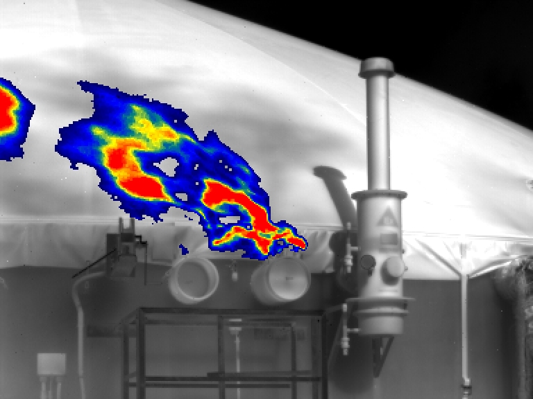
In order to meet the requirements of TRAS 120, it makes sense to check the system at regular intervals using a methane-sensitive optical method. Gas visualisation by means of an infrared camera makes use of the specific gas properties of organic gases in certain wavelength ranges to absorb a particularly large amount of thermal radiation. The working range of the IR gas camera is limited to a methane-specific wavelength range (7.8 µm) by a narrow-band filter, so that less radiation from the image background reaches the highly sensitive light-sensitive focal plane array detector when gases occur. The resulting temperature change causes a photon flux. This is converted into a digital signal in a readout circuit and then visually displayed. Emerging gas becomes visible on the display in the form of a cloud. The recorded image is displayed in real time and can be saved as a film sequence for documentation purposes.
From the context shown, it is clear that a temperature difference between the gas and the background is required as a basic prerequisite for visualisation. Since the camera has a thermal sensitivity of <10 mK (milli-Kelvin), this condition is in fact always met for gas leaks at biogas plants.
Gas cameras do not have a radiation source. The ambient radiation present in the atmosphere is collected via an infrared object, limited to the wavelength characteristic of the gas via a bandpass filter and evaluated by a cooled sensor array. If infrared radiation is absorbed by a methane gas cloud, this can be detected via the camera in a video sequence.
Visualisation of GasCam
Regular inspection for leaks
Another requirement of TRAS120 states that the exhaust air flow of the interstitial space must be checked for leaks on a weekly basis. Two possibilities are shown below to ensure uncomplicated measurement without the use of a climbing aid or ladder.
1st option: Measurement via hose connection along the edge of the container
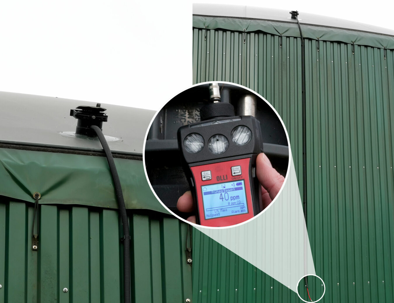
As shown in the picture, a hose connection is installed from the blow-out opening along the edge of the container. By using an appropriate adapter and a gas detector, the gas concentration of the interstitial space exiting via the blow-out unit is obtained within a few seconds.
2nd possibility: Measurement with industrial probe set
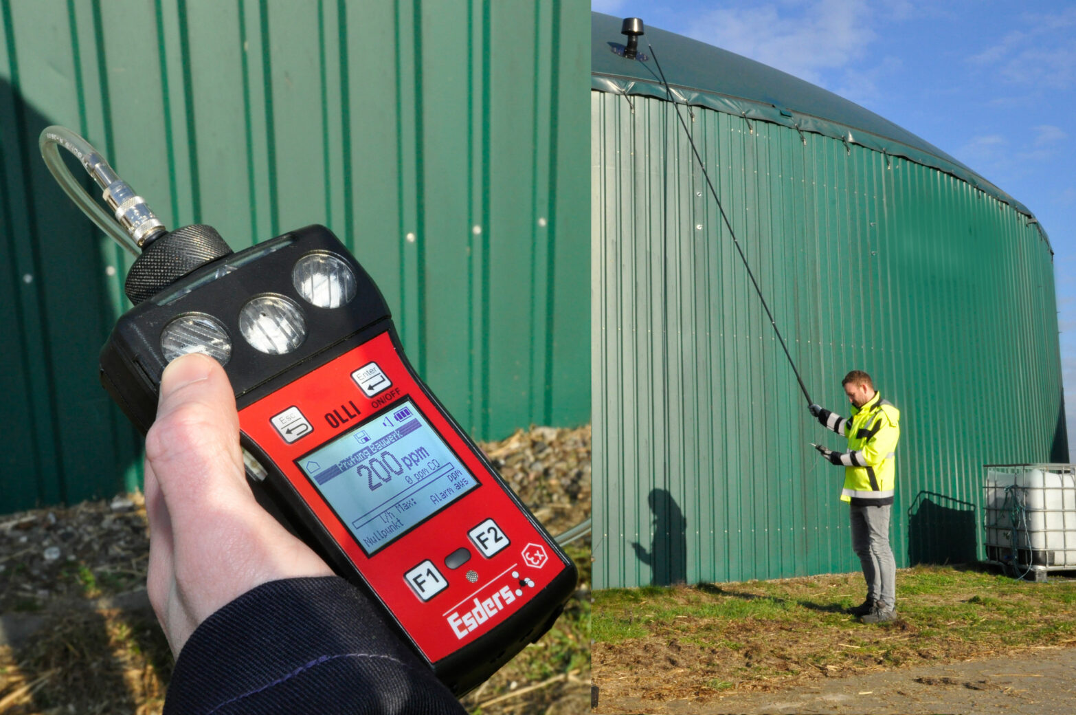
By means of probes that can be screwed together, it is possible to extend the probe system up to 5 metres in order to measure the gas concentration of the exhaust air flow from the ground on the one hand and to check for leaks at higher locations, such as a support air roof on a biogas plant, on the other.
With the information on leak detection and remote detection with the help of a GasCam, I would now like to conclude the series of blog posts on the topic of biogas for the time being. The most important areas in connection with gas measurement on biogas plants have been covered. Starting with personal protection on biogas plants, we dealt with the analysis, i.e. the measurement of the individual gas concentrations of the raw biogas, in the second blog article. In all articles we dealt with problems occurring on biogas plants and tried to counteract these problems in a solution-oriented way. In addition, possibilities for measurement with the help of gas measuring devices were shown.