Table of Contents
Technical rule – Technical standard DVGW G 469 (A) July 2019 Pressure testing procedures gas transmission/ gas distribution – The changes compared to DVGW G 469: 2010-06 summarised and explained.
Why did changes have to be made at all? First and foremost, it is certainly clear to everyone that there are many technical innovations in nine years and that new possibilities for pressure test methods arise from this. For this reason, the worksheet had to be revised and brought up to the latest technical standard.
In the following remarks, we will concentrate on the points that concern us as a measuring instrument manufacturer.
Overall, times and specifications have become more concrete.
There was a lot of discussion about the topic of testing times and whether these can be reduced overall. Here I had to object quite clearly, because from our point of view this is not possible.
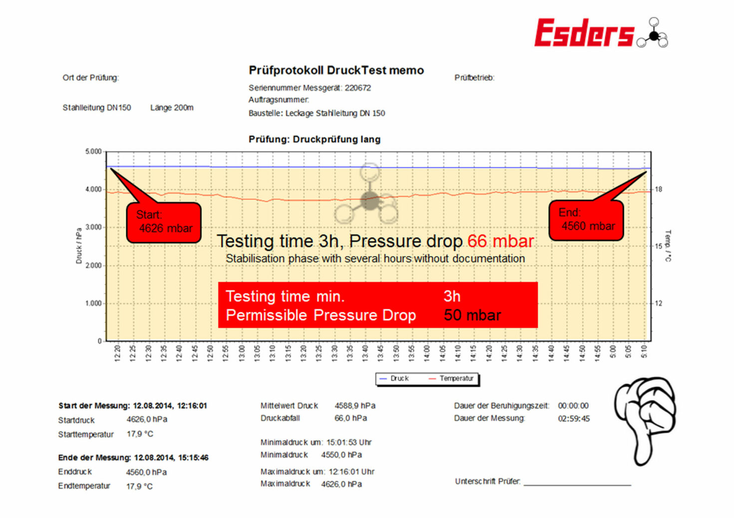
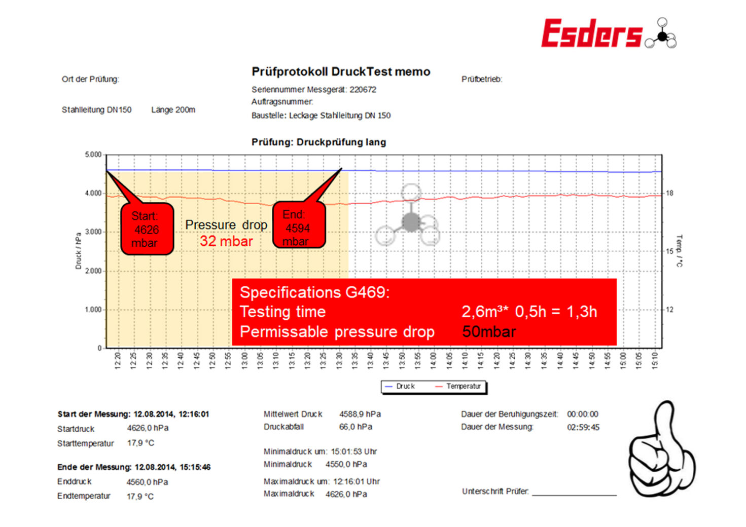
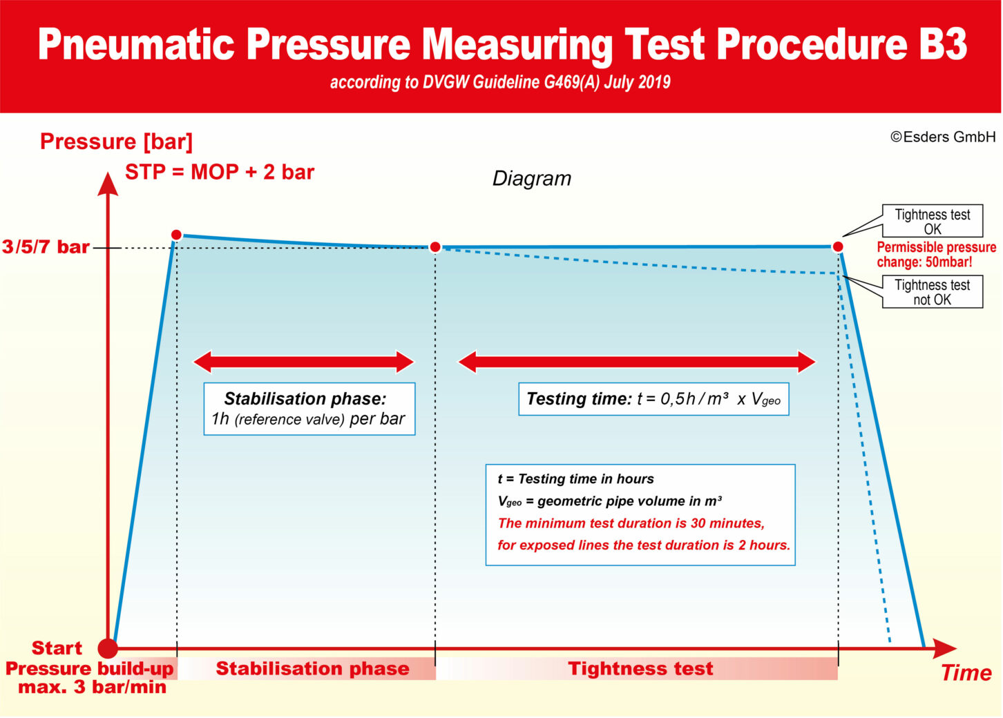
As an example, we would like to mention an industrial company whose gas pipeline for technical gases was to be subjected to a pressure test similar to procedure B3. The factory standard was a maximum permissible pressure drop of 50 mbar, but for a minimum test time of 3 h. The test was carried out in accordance with G 469. According to G 469, a calculated test time of 1.3 h would be necessary. In practice, 1.5 h would probably have been tested and recorded.
The pressure test was carried out as part of the presentation of our measuring devices as a service. This resulted in a pressure drop of 66 mbar in 3 h, which is outside the company’s specifications. However, this is only a drop of 32 mbar within the mandatory testing time of G 469. To find the suspected small leak as quickly as possible, forming gas with 5% hydrogen and the rest nitrogen was injected. With our hydrogen detector HUNTER Tracer Gas, a leak could also be located. This was repaired immediately and the pipeline was then put back into operation.
With improved scaling and higher resolution, the continuous pressure drop due to leakage becomes visible.
In my view, this example clearly shows that the requirements of G 469 are by no means excessive and should definitely not be loosened. This is also agreed with by many of our customers who also specify stricter limit values for the pressure tests in their operating instructions and have had good experience with doing so.
The requirements for measuring equipment have been revised (chapter 3.6 Requirements for measuring instruments). The required protection class for measuring devices has been increased from IP 65 to IP 67. A rechargeable battery no longer has to be sufficient for at least 1.5 times the test duration.
General
- For electronic measuring instruments it is no longer applicable that the internal power supply is sufficient for at least 1.5 times the test duration.
- Unless special protective measures are taken (e.g. measuring trolley), the pressure measuring device shall be protected against external influences in a lockable container of protection class IP 67 (old was IP 65).
It was decided that mechanical pressure recorders no longer represent the current state of the art and are therefore no longer permitted. It is important for us that pressure measuring devices must always be used for test procedures.
Pressure measuring devices for pressure measuring test procedure B3
- An electronic, recording pressure measuring device is required as a pressure measuring instrument.
Mechanical pressure recorders are completely obsolete and no longer permitted.
The innovations
- Introduction of Pneumatic Negative Pressure Test E 3
- Supplementary notes on relative pressure sensors for Pneumatic Precision Pressure Measuring Procedure C 3
- Specification of the test pressure for the Visual Inspection, Pneumatic A 3
- Additional note for the Visual Inspection with Gas A 4
- Omission of the obligation to carry out the exhaust gas test for Pneumatic Precision Pressure Measuring Procedure C 3
Pneumatic Negative Pressure Test
Classification of pressure test procedures – NEW – Pneumatic Negative Pressure Test
During the Pneumatic Negative Pressure Test procedure a weld seam is tested with foam-forming agents under vacuum.
Description of the pressure test procedures
Visual Inspection A
- The pipe connections to be tested must be accessible and free of grease, coatings and paints. Any deviations must be agreed with the expert before the pressure test is carried out. In addition, the lighting conditions must be sufficiently good for the test (new section).
- For procedures A 1, A 2 and A 3, a recording pressure measuring device shall be used to document the test pressure. For procedure A 4, the test pressure/operating pressure of the upstream/downstream system must be documented.
Visual inspection, Hydrostatic (Single Application) A 1
After the test pressure has been applied at a specified pressure increase (up to a maximum of 3 bar/min) and held for 1 hour (previously usually 3 hours), the pipe or system is kept at the test pressure until all connections have been tested for leaks.
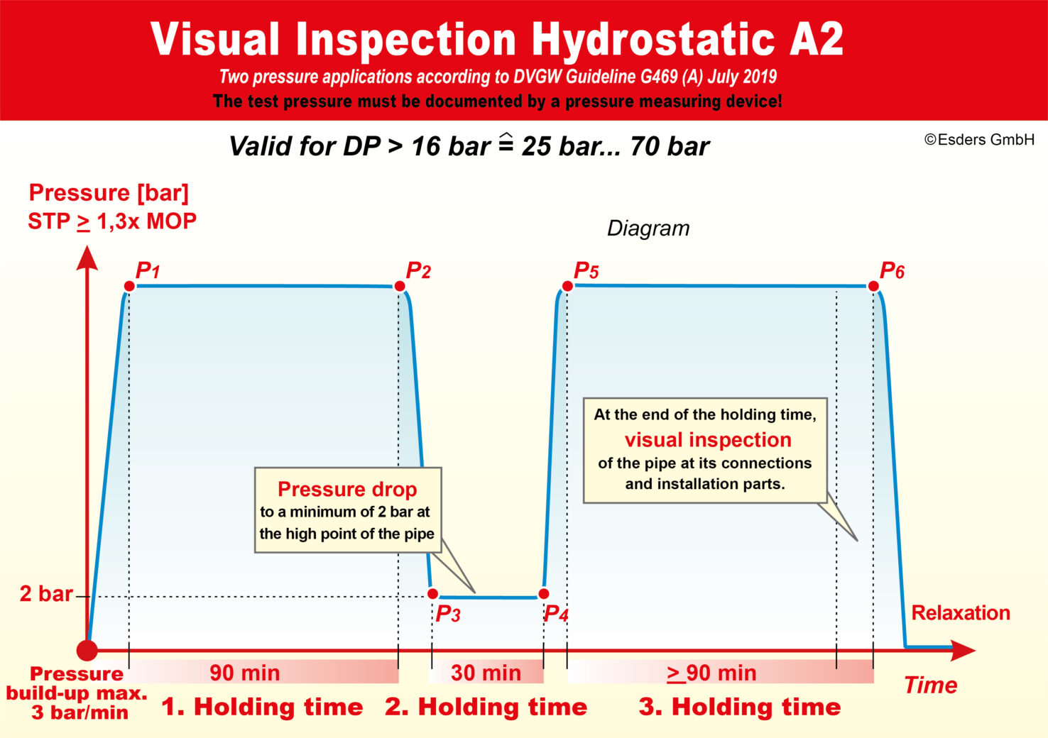
Visual inspection, Hydrostatic (Two Pressure Applications) A 2
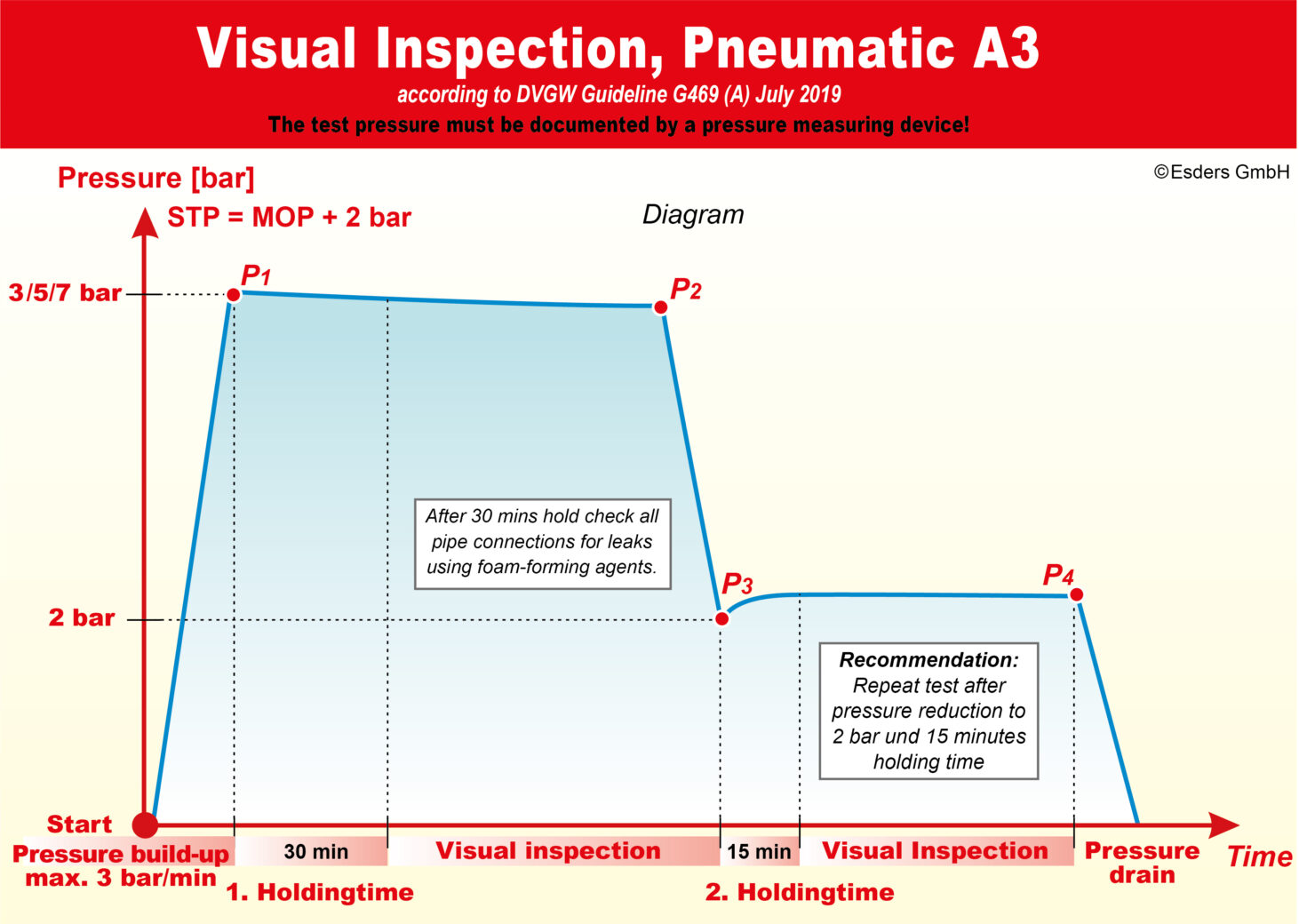
Visual Inspection, Pneumatic A 3
- The test pressure is 1.1 times the maximum permissible operating pressure, whereby the test pressure must exceed the maximum permissible operating pressure by at least 2 bar.
Restrictive regulations for the application of this procedure in the DVGW technical rules applicable to the pipeline or system must be followed.
After lowering the test pressure to approx. 2 bar (lowering speed max. 3 bar/min) and a holding time of 15 minutes, it is recommended to repeat the test with lowered pressure using a foaming agent.
Here we have more precise specification of test pressure, lowered test pressure and holding time than before.
Pressure Measuring Procedures B
Hydrostatic Pressure Measuring Procedures B 2
- The test sections should not exceed a length of 15 km and a volume of 6,000m³ (previously 3,000m³)
Pneumatic Pressure Measuring Test Procedure B 3
- The test procedure is applied to pipes that are as completely buried as possible. Exposed parts of the pipes must be protected against temperature influences (e.g. frost or sunlight).
The following sentence is omitted completely:
Otherwise, the temperature influence on exposed parts of the pipe must be taken into account.
New paragraph:
To avoid damage to pipes and fittings made of PE when air is used as the test medium, oil from the compressor must be prevented from entering the pipeline. If necessary, a compressor with aftercooler must be used to press on the PE pipe in order to avoid damaging, temperature-related influences on the PE pipe.
Pneumatic Precision Pressure Measuring Procedure C 3
General
If there are no obvious influences on the temperature of the buried pipeline section(s), the precision measurement method can be used without measuring the earth temperature.
NEW: The geometric pipe volume of 100 m³ should not be exceeded.
The following section has been omitted:
Both direct measurement by means of a precision pressure measuring device and indirect measurement by means of a differential pressure gauge and precision pressure measuring device for pressure maintenance can be used as a test method.
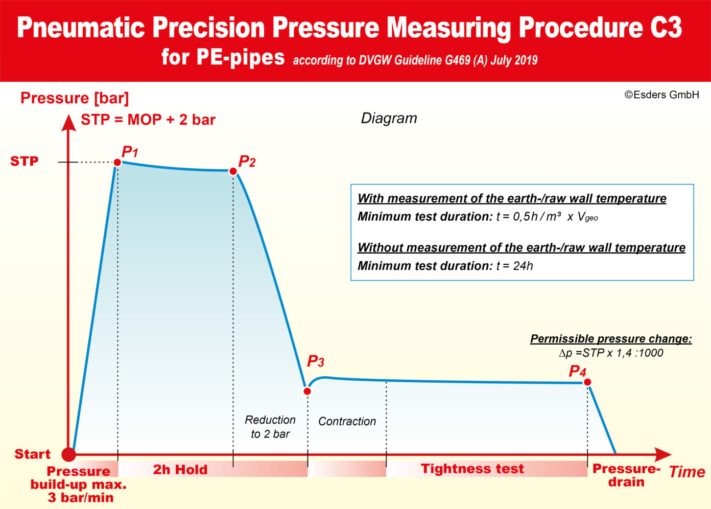
Special characteristics when testing PE pipes
In order to take into account, the viscoelastic properties of the material PE, the following procedure is recommended: After the test pressure has been built up, it is maintained for a period of 2 hours. Then the test pressure is lowered to approx. 2 bar. After completion of the contraction phase, the leak test is carried out with the lowered pressure according to procedure C 3. For the calculation of the permissible pressure change, the test pressure before the pressure reduction is used.
There are modified times for performing this special PE test. The procedure with time duration and permissible pressure change are as for normal execution, after the pressure reduction and completion of the contraction phase.
Pneumatic Negative Pressure Test E 3
The negative pressure test method is suitable as an alternative test method for leak tests on weld seams of gas pipes and gas-technical containers that cannot be directly pressurised.
The vacuum pump evacuates the space under the test frame of the vacuum goggles.
If there are leaks in the weld, the foam-forming agent in combination with the negative pressure creates bubbles under the test fixture in a few seconds.
The test vacuum must be in the range of 200 to 500 mbar. The vacuum goggles must cover the area of the weld seam for at least 30 seconds without additional fixation.
The test device used, the test vacuum, the test duration and the foaming agent used must be documented.
In the area of vacuum testing technology, we noticed a video by the company VIETZ Schweißtechnik from Leipzig, which explains this procedure very clearly.