

Table of Contents
Gas service connections are often treated somewhat stepmotherly. From time immemorial, these have tended to be simple pressure and leakage tests, for which less investment was often made in equipment technology. But when you look at the hazards and what is most susceptible to faults, is what is directly in front of the house or goes into the building. The danger for us humans is much greater here and much more probable than with a supply line that runs along a country road. This should be kept in mind again and again. Accordingly, the tests should not be played down, but should be carried out with absolute care.
German gas damage statistics from 2019 (source DVGW) show clearly that:
- Supply pipelines up to 16 bar and > 16 bar account for three times as much in million km of gas network compared to house connections.
- In the case of mains connections, almost twice the numbers of events requiring immediate reporting per year occur.
Advantages through documentation
If we carry out an inspection using the latest measuring technology, we can document the condition of a newly laid pipeline at a specific time. This is not primarily a monitoring of those who install the pipe. On the contrary, the person carrying out the inspection proves and documents the safety and quality of his work.
The underlying set of rules for the performance of pressure tests on gas pipelines is described in DVGW Code of Practice G 469 (A) 07/2019.
After construction of a pipeline or plant, it must be demonstrated by a pressure test that it is suitable for operation at the intended permissible operating pressure.
The commissioning of pipes and plants is not permitted without proof of a successfully completed pressure test.
Which of the pressure test procedures described in this Code of Practice G 469 is used and who is authorised to accept the pressure test is specified in the Technical Rules of the DVGW for the construction and operation of gas supply pipelines and installations with reference to this Code of Practice.
Pressure test methods gas transport/gas distribution
Purpose of the test: The pressure test methods described here can be used alone or in combination.
They are used to assess the strength and/or tightness of the tested system and thus help to prove the safety of the pipes or installations.
Other reasons:
- Acceptance of the line
- The contractor (pipeline constructor) shall provide the customer (supplier) with evidence of proper execution of the work proof of safety for commissioning (admission of gas).
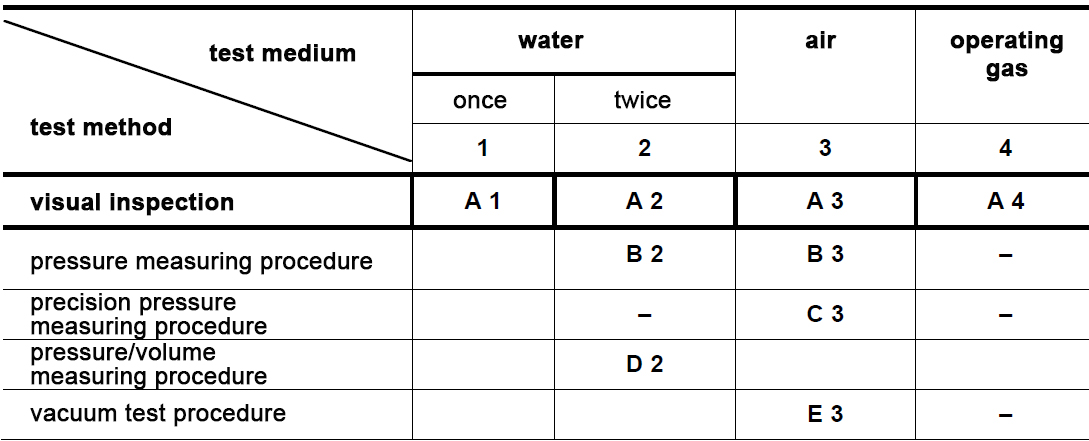
The procedures are classified according to whether:
- The pipeline or plant under test pressure is inspected from the outside during the test period (visual method)
- The test pressure in the pipe or installation is measured during the test period (pressure measurement method)
- The test pressure in the pipe or installation is measured during the test period with a precision pressure gauge (precision pressure measuring method)
- In addition to the test pressure in the pipeline, the quantity of water to be re-pumped, which causes an integral permanent circumferential expansion of the pipeline, is measured (pressure/volume measurement method)
- New: A weld seam is tested under vacuum with foam-forming agents (vacuum test method)
Regardless of the classification, the pressure test methods differ in that a liquid test medium (water) or a gaseous test medium (air, operating gas) is used for the pressure test. For water, other suitable liquid test media can also be used and for air, other suitable gaseous test media can also be used. Instead of operating gas, mixtures of operating gas and inert gases (usually nitrogen) can also be used as test media.
Test method and test medium
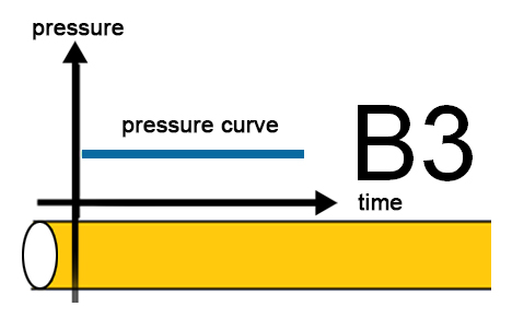
Pressure test method G 469 B3
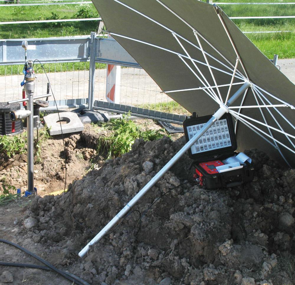
Device Technology
- For the B3 test an electronic, writing pressure measuring device with accuracy better than 1/3*50mbar =17mbar is prescribed.
- This must have an initial certification and be tested annually.
- In addition, a control manometer (measuring range 1.5x STP) is used.
For maximum allowable operating pressures (MOP) less than or equal to 5 bar
The test pressure must exceed the permissible operating pressure by at least 2 bar.
Example: MOP =1 bar → STP practical 3.1…3.5 bar
The duration of the pressure test is determined as follows:
t = Vgeo * 0.5 h/m³ (where t = test duration in h and Vgeo = geometric pipe volume in m³)
The minimum test duration is 30 minutes; for exposed lines, the minimum test duration is 2 hours.
The test procedure is applied to lines that are earthed as completely as possible. Exposed line parts must be protected against temperature influences (e.g. frost or solar radiation).
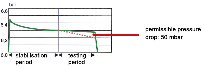
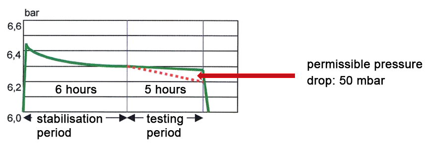
The permissible pressure drop is 50 mbar.
After applying the test pressure (pressure increase max. 3 bar/min) and reaching the steady state, the measurement starts. As a reference value for the temperature adjustment, one hour can be assumed for each 1 bar test pressure, if the adaptation time cannot be shortened by suitable measures (e.g. compressor with aftercooling).
Amendment G 469 07/2019
If air is used as the test medium, oil from the compressor must be prevented from entering the pipeline to avoid damage to pipes and fittings made of PE. If necessary, a compressor with aftercooler must be used to press on the PE line to avoid damaging temperature-related influences on the PE line.
Summarised
Test pressure: STP = MOP + 2 bar
Stabilization time: 1h / bar
Test time (earthed cable): t = Vgeo* 0.5 h/m³ (min. 1/2h)
Test time (exposed cable): t = Vgeo* 0.5 h/m³ (min. 2h)
Reminder: Avoid influence of temperature!
Practical example:
Distribution line MOP 4bar; 10 m³; line earthed
Test pressure: nSTP = 4 bar + 2 bar = 6 bar
Stabilisation time: 1h / bar = 6 h
Test time (earthed cable): t = 10m³ * 0.5 h/m³ = 5 h
B 3 Service line test
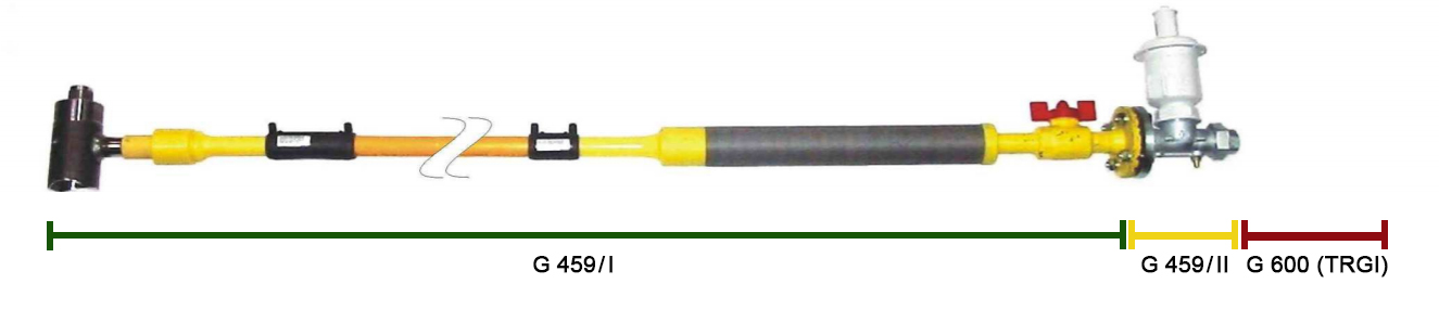
These are the requirements to finally arrive at the examination of the house connection according to worksheet G 459-1 (A) 10/2019.
According to NDAV (Low Pressure Connection Ordinance), the network connection begins with the outlet from the supply line. The network connection ends with the main shut-off valve (HAE) and includes the gas pressure control according to DVGW worksheet G 459-2, if available. Outside the network connection the G 600 TRGI is used.
Prior to commissioning, the network connection must be tested according to DVGW worksheet G 469, taking into account the maximum permissible operating pressure, by means of a pressure test including the opened HAE.
This also applies to the connecting line between HAE and gas pressure regulator. The pressure test must be carried out with the gas flow monitor open and shut-off valves must also be checked for proper functioning.
If the network connection is tested together with a supply line, the pressure test is carried out according to the pressure test procedure of the respective DVGW worksheet for the supply line.
Personnel
The network operator must ensure that the activities are carried out by a professional individual. This person has to be qualified and experienced and appointed either by the network operator or the customer.
After a completed and successful pressure test, the positive result of the pressure test must be confirmed and documented by a qualified person.
The pressure test can be carried out according to the visual procedure with air (A3) of DVGW worksheet G 469. The test pressure must exceed the maximum permissible operating pressure by at least 2 bar.
If, for example, the pressure measurement procedure with air (B3) of DVGW Code of Practice G 469 is used for laying in casing pipes or trenchless laying, the settling time and the duration of the pressure test can be reduced to 15 minutes each, in deviation from the Code of Practice.
If, for operational reasons, a test using the visual method with air (A3) or the pressure measurement method with air (B3) is not possible, e.g. in the case of joints under gas, a pressure test using the visual method with service gas (A4) can also be carried out. The joints must then be tested for leaks with foam-forming agents according to DIN EN 14291 or with suitable gas concentration measuring devices.
In general, the pressure measuring procedure, the B3 test, is carried out and documented with a pressure measuring device.