

The DVGW Worksheet W 400-2 explains different methods for hydrostatic testing of pipelines in more detail.
In addition to the pressure loss method, there is the water loss method and the visual inspection with operating pressure.
What must be taken into consideration during visual inspection with operating pressure?
Connections to a new pipeline section cannot be subjected to an independent pressure test. During the visual pressure test, the pipeline sections must be exposed, with the exception of the ring coil. Here it is sufficient if only the joints are visible. Connections, repair work and new pipeline sections up to a maximum length of 30 m (without restriction regarding the nominal diameter) and a maximum of five pipe connections are to be tested.
Tightness shall be verified in particular at the joints by a double inspection at intervals of at least one hour.
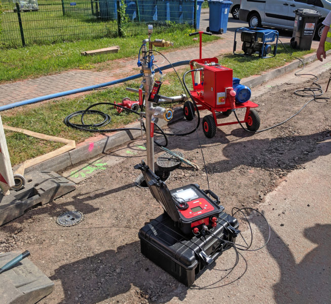
Recommendation: We as a company also recommend documenting the activities by recording a print log with the measuring device for the duration of the pressure test. As a rule, the equipment is available at the client’s premises and hardly any additional work is required. This shows professional work even with a simplified procedure. Date, time and test pressure, as well as the test time are visible and comprehensible.
What is to be taken into account with the pressure loss and water loss methods?
Four different methods can be used for the pressure loss and water loss method, depending on the material of the pipeline:
- the accelerated standard method for pipelines made of ductile cast iron and steel with cement mortar lining
- the influence-minimized normal method
- the contraction method for PE and PVC pipelines
- the standard method for all pipelines
During each of these tests the influence of temperature on the pipeline must be taken into account. The temperature of the outer wall of the pipe should not exceed 20 °C. Particularly with PE and PVC pipes, a higher temperature and long test duration, such as with the standard procedure, has an effect on the test result of the pressure test, since the pipe material expands when exposed to heat. Exposed pipe sections must be protected from direct sunlight by covering them. Too high temperatures as well as temperature changes have a strong influence on the course of the pressure test. The service life of the pipe can also be reduced by excessively high temperatures in conjunction with high test pressures.
Test sections and test pressure
The test method, the procedure and also the test pressure are determined by the client.
The test pressure can be calculated. We speak here of the System Test Pressure (STP) and need the MDP (Maximum Design Pressure/Highest System Operating Pressure) for the calculation. The value of the MDP is determined by the operator (e.g. 10 bar).
The following calculation is without shock pressure calculation:
STP = MDP x 1.5
or
STP = MDP + 5,0 bar
The lower value applies for further use.
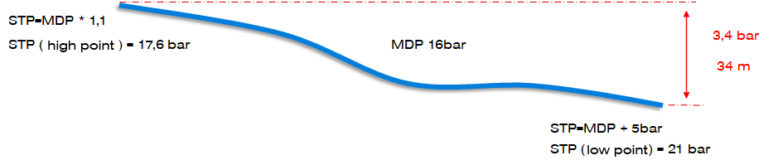
The pipeline shall be tested as a whole or, if necessary, divided into sections. The test sections shall be defined such that the test pressure STP is reached at the low point and at least 1.1 times the value of the system operating pressure MDP is reached at the high point. The required amount of water must be provided and it must be possible to discharge it without difficulty, or it must be possible to produce the test pressure STP within a specified time.
The measuring devices required for the test should be connected to the lowest point of the test section. A height difference influences the pressure in the pipeline; 10 m water column corresponds to approx. 1 bar pressure difference. If we connect the measuring device to the pipeline at a high point in hilly terrain, the pipeline can be overloaded during the test. This is because the pressure at the low point is made up of the test pressure at the high point plus the pressure resulting from the geodetic height.
Pressure difference at high and low point
Required equipment technology
- Recording electronic pressure gauges: resolution 0.01 bar
- Control pressure gauge: Resolution ≤ 0,1bar
- Temperature sensor: Resolution ≤ 0,1K
- Water meter: Resolution ≤ 0,01Liter, subdivided according to the amount of water that is e.g. drained
- Overpressure protection
- Pumps: Hand pumps or electric pumps (for plastic pipes with a volume of > 0.1 m³ or more)
What is the water loss method?
Explained here using the example of the accelerated normal method (internal pressure test for pipes made of ductile cast iron and steel up to DN 600 with cement mortar lining)
- rarely used measuring method
- technically only to be realized with great effort
- Air inclusions can be neglected
The water loss method describes a pressure drop test.
Air in the pipe to be tested is problematic because it simulates tightness in case of slightly leaking pipes. The pressure drop test enables us to make a statement about the residual volume of air remaining in the pipe. Following the preliminary test and saturation phase, a quantity of water is taken from the pipeline, which must be measured in order to achieve a pressure drop corresponding to the respective nominal diameter range.
Main test for the water loss method
The main test takes one hour. The permissible saturation-related water loss is calculated with:
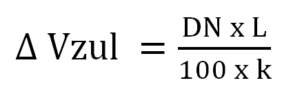
∆ Vzul = permissible water loss (cm3 )
k = proportionality factor, k = 1m/ cm3
DN = Nominal diameter (without unit)
L = Pipe length (m)
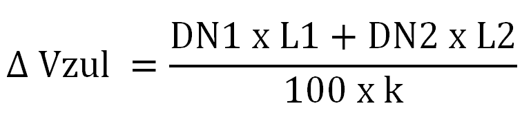
If the present test section consists of pressure pipes with different nominal diameters, the permissible water loss can be easily calculated using the following formula:
The loss of water is accompanied by a drop in pressure, which is compensated by adding water at the end of the main test. This restores the system test pressure.
The volume of water added corresponds to the actual water loss during the main test.
The volume can only be determined with great effort during the addition of water, especially for small quantities. Therefore we can determine the volume more easily after reaching the system test pressure: by subsequently draining and collecting the water in the measuring cup until the pressure measured at the end of the one-hour main test is reached. If the actual water loss ≤ ∆ Vzul, then the pressure supply line is considered to be tight and the test is passed.
In the third part of our blog series on the basics of water pressure testing, we go into detail about the pressure loss method. The pressure loss method is the most commonly used measuring method in Germany and can be realized technically without much effort. For this reason, the DVGW recommends the pressure loss method for conducting pressure tests.
Do you need advice?
You have now gained a deeper insight into the various procedures of water pressure testing according to W 400-2. It is clear that this task requires a lot of technical know-how and precision. At Esders, we pride ourselves on having this expertise and making it available to our customers. We are ready to assist you with your pressure measurement challenges and ensure that your systems meet the highest standards.
Don’t hesitate to contact our technicians to learn more about our products. We will get back to you in a timely manner!