

Table of Contents
In the following explanations we try to clarify the problems of pressure tests. For complete training courses, we offer practical seminars on our test track in Haselünne.
For hydraulic pressure test, we consider the head loss method procedures in detail. These are:
- The accelerated procedure for pipelines made of ductile cast iron and steel with cement mortar lining
- The influence-minimized standard procedure
- The contraction test for pipelines made of PE and PVC
- The standard procedure for all pipelines
Since the standard procedure can take three to four days in practice and the work on a construction site should progress as quickly as possible, the accelerated procedure was developed.
The Accelerated Procedure
The accelerated procedure is an internal pressure test for pipes made of ductile (expandable) cast iron and steel up to DN600 with a cement mortar lining.
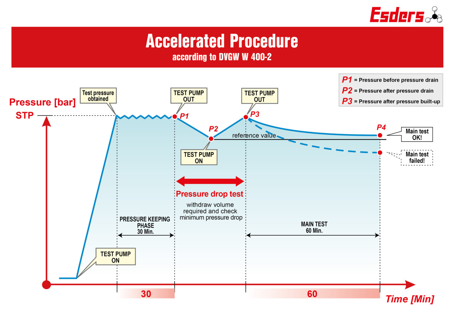
Preliminary / Pressure keeping phase
The test pressure STP (System Test Pressure) is applied. There is no limit in which the print task has to take place. To achieve a high degree of saturation, the test pressure STP is maintained for half an hour by pumping continuously is primarily decisive for saturation. A too low pressure cannot be balanced by extending the pressure keeping phase.
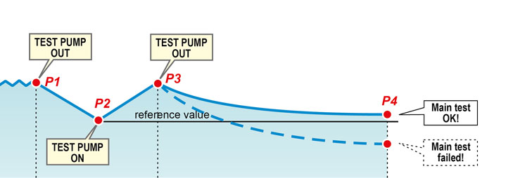
Pressure drop test
A calculated water volume Verf. Is taken from the pipeline section to be tested at the test pressure STP.
The resulting pressure drop Δp is measured. The line is considered to be adequately vented if the measured pressure drop Δp is greater or equal to the minimum pressure drop Δpmin specified in the table when the water volume Verf. Is withdrawn.
After a successful pressure drop test, the pressure must be established again to STP.
Main test
The pressure drop Δp (P1-P2) measured during the pressure drop test is the permissible drop Δpzul in the main test.
The line is considered to be tight if the pressure drop in the main test is constantly decreasing at the same time intervals and does not exceed the permissible pressure drop Δpzul over the duration of the main test. Since it is assumed that the pressure drop is essentially to the saturation of the cement mortar lining and that the saturation is continuously decreasing, it is required that the pressure drop does not remain the same at the same time intervals. Because a linear pressure drop indicates a leak!
A too low pressure cannot be balanced by extending the pressure keeping phase.
Sign up for our newsletter and stay informed
If you would like to be kept up to date with changes to regulations, new products, news on the blog and much more, please fill in the form below.
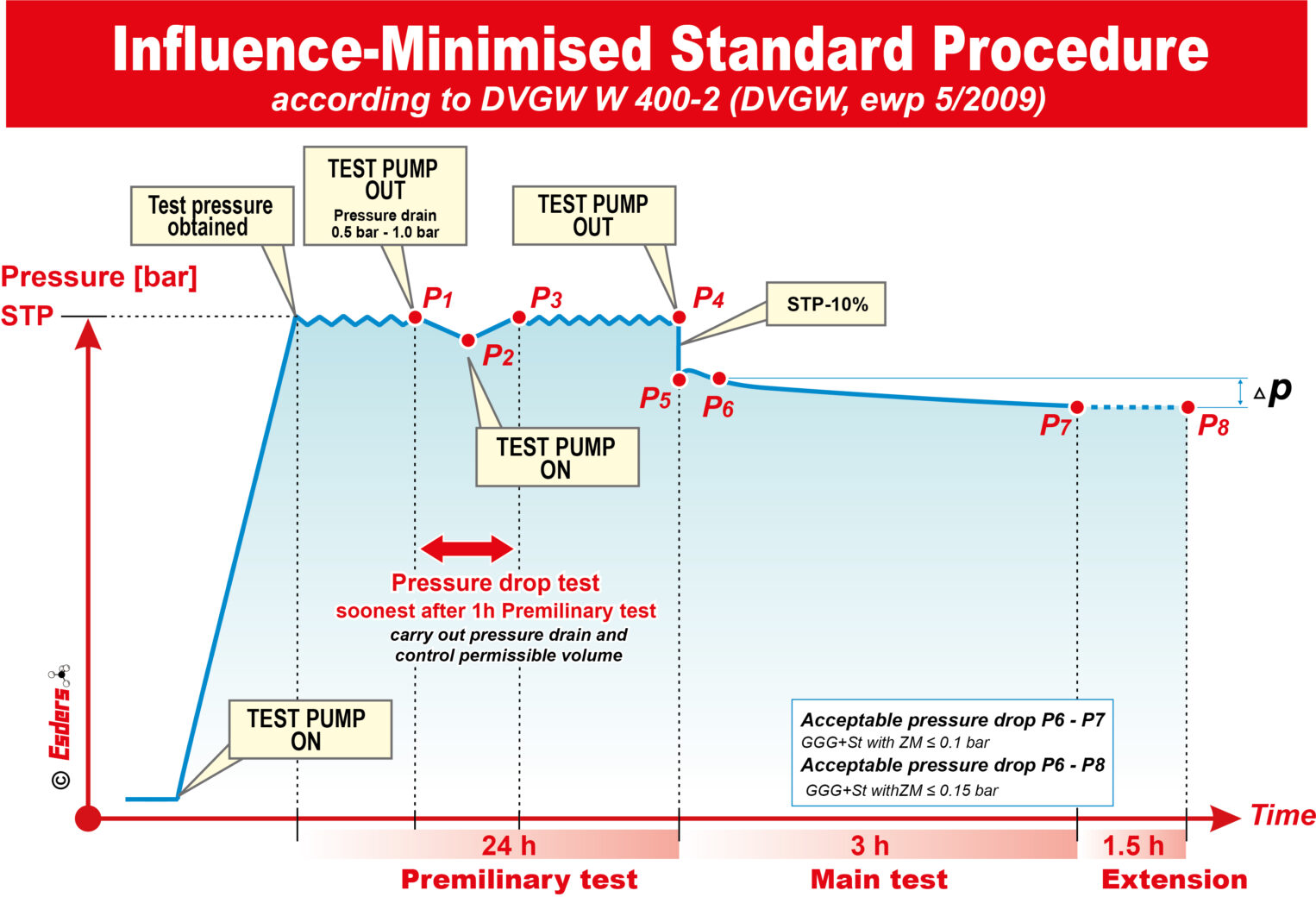
Influence-Minimized Standard Procedure
The influence-minimized standard procedure is a special test method for larger pipelines ≥ DN 400 with cement mortar lining and works exclusively using the head loss method. This procedure takes at least two days. Practice shows that it can take more than a week to achieve full saturation. The influence-minimized standard procedure was developed because in the work routine pipelines with very large nominal diameter are difficult to test or only over very long periods of time. This is due to air pockets in the pores of the concrete. The solution is to choose a large pressure drop of 10% of the test pressure. As a result, the air still presenting in the pores of the lining has less influence on the assessment.
Preliminary test with integrated pressure drop test and subsequent pressure reduction
The preliminary test lasts 24 hours and the process is carried out as in the standard procedure. If the integrated pressure drop test and the further pressure maintenance are successful, the preliminary test is finished. The pressure is than reduced by approx. 10% (e.g., from 21 bar to 19 bar for pipelines for MDP = 16 bar).
Main test
After the pressure drop, there is a slight increase in pressure, depending on the cement mortar lining. The subsequent pressure gradient is observed for 3 hours in order to minimize temperature fluctuations. The test time can be extended by further 1.5 hours or until the temperature is equalized during the day. From the end of the pressure increase, the pressure must not drop by more than 0.1 bar or 0.15 bar (with an extension of 90 minutes).
The Contraction Procedure
Important features to consider:
- PE and PVC pipelines show a viscoelastic expansion behavior.
- The expansion behavior is interrupted by a rapid drop in pressure.
- The drop in pressure leads to a contraction of the pipe. This is what gave the process its name.
The pipe temperature must be between 5°C and 20°C. We have experience from customers who have tested several lines at a temperature of 7°C in one day with negative results. The same pipes passed the test the following day at approx. 11°C without any problems.
Changing temperatures in a large part of exposed route, e.g., due to solar radiation, are also problematic. This should always be taken into account for a successful test.
From a pipe volume of 20m3, the set of rules recommend to carry out the standard procedure. This is due to the fact that it is becoming more difficult to build up pressure within the prescribed 10 minutes.
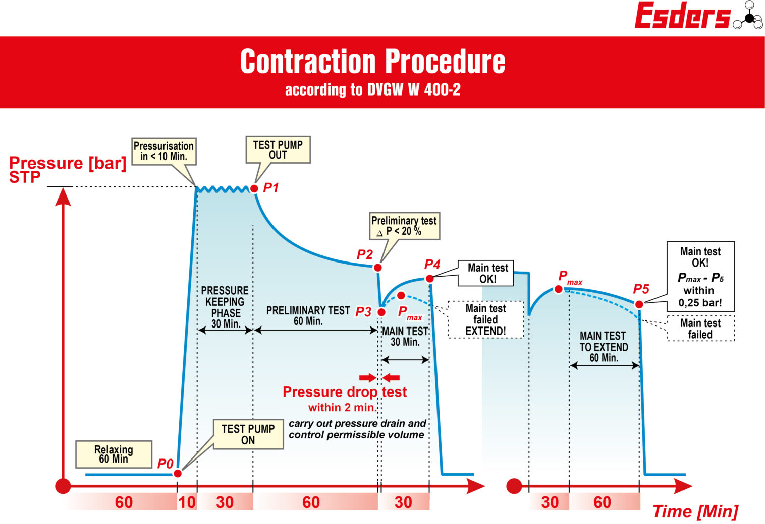
Relaxation phase
After the pipe section to be tested has been filled with drinking water and has been vented, the pipeline must be depressurized for one hour. The aim of this is to reduce pressure-dependent tensions in the pipe wall. No air my get into the test system.
Pressurization phase
After the relaxation phase, the STP should be applied continuously and quickly (within 10 minutes). We are often asked whether the 10 minutes should be adhered exactly. The subsequent relaxation and contraction largely depend on the rapid build-up of pressure. Nobody can exactly define a limit. But if the further phases and results are positive, a time of 12 to 13 minutes would also be acceptable and unproblematic for us.
Pressure keeping phase
The system test pressure is maintained over a period of 30 minutes by pumping continuously or at intervals. Here you can see the most varied pump solutions in practice at customers’ sites. A provision of simply switching the pump on and off is not contemporary and often causes pressure fluctuations in the range of several bars. The rate should fluctuate a maximum of 1 bar around the STP. Appropriate test pumps do this much better, even with small pipe volumes.
Preliminary test
In the one-hour rest phase (preliminary test), the pipeline expands viscoelastic.
Pressure drops of ≥ 20% within the preliminary test lead to the test being aborted. The test section is to be examined for leaks. The test must be repeated at the beginning of the relaxation phase.
If the preliminary test is successful (pressure drop <20%), the test can be continued.
Drain test
A basic prerequisite for assessing the tightness is sufficient ventilation, which is verified with the drain test.
A rapid pressure reduction (<2min) by a specified pressure must be carried out.
The drained water Vab must be measured and must not exceed the permissible water volume Vzul. A sufficient ventilation is only proven with Vab≤Vzul.
If the water volume is higher than permitted, the test must be aborted. By rinsing again, ideally pigging, freedom from air is established.
This pressure reduction and water withdrawal is not that easy. Very little has to be removed, especially with short pipe sections and low internal volume of the line and at a pressure around 15 bar even this water is quickly splashed to the side. Therefore, it is important that the operating personnel practice this and get a feel for the pressure release and extraction.
Main test
The viscoelastic expansion of the pipeline is interrupted by the rapid pressure drop during drain test.
This leads to a contraction of the pipeline. The increase in pressure caused by the contraction must be recorded for a period of 30 minutes (main test).
The main test has been passed if the pressure line that appears over the course of the 30-minute contraction time shows an increasing or constant tendency.
If the pressure line shows a downward trend during this time, this indicates a leak within the test section.
The test duration must then be extended by 60 minutes. The pressure drop must not be more than 0.25 bar, measured from the maximum value within the contraction phase.
If the pressure falls by more than 0.25 bar, the extended main test has also failed.
The test is successful if the following criteria are met:
- Pressure drop 20% STP during the preliminary test
- Proof of freedom from air pressure reduction established with Vab ≤ Vzul
- Increasing to constant tendency during the main test (or passing the extension with ΔP ≤ 0.25 bar)
The Standard Procedure
The standard procedure is suitable for all materials and all dimensions. It is often used when the faster methods cannot be used due to the length of the line or the dimension.
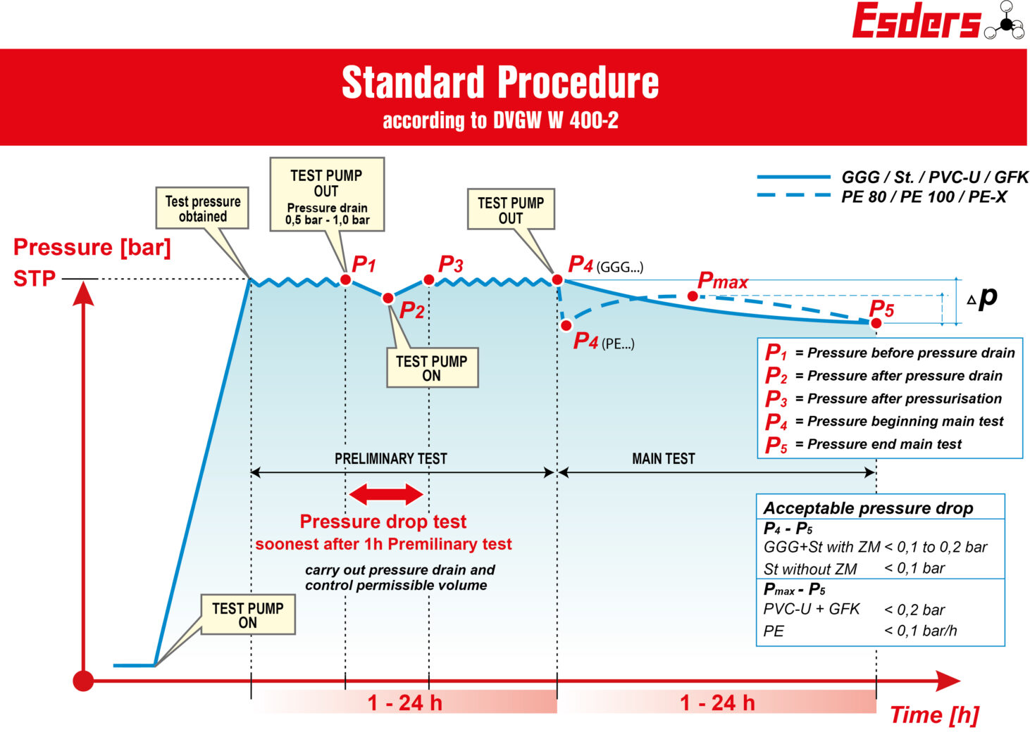
Course of the test
- Fill air-free
- Pressure build-up phase without time limit
- Preliminary test: 1h to 24h, depending on the material and DN
- Pressure drop test: without time limit
- Main test: 1h to 25h, depending on the material and DN
Pressure drop test
The pressure drop test takes place at the earliest one hour after the start of the preliminary test. Withdraw a quantity of water so that there is a pressure drop of 0.5 bar in the pipeline (small DN / short pipe pressure drop 1 bar).
- The following applies: ΔV ≤ ΔVzul
If the drained volume is less than the permissible volume, the pipe is sufficiently vented.
The permissible volume is calculated using the following equation:
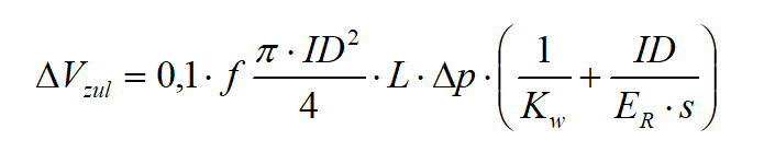
Vzul maximum permissible water volume in ml
Δp measured pressure drop (0.5 bar or 1 bar)
ID pipe inside diameter in mm, without taking into account the ZM lining
KW compression module of water in N / mm2 (2027 N / mm2)
ER modulus of elasticity of the pipe material in N / mm2
For all of us who took math lessons a long time ago the formula looks complicated. Essentially, it is the volume of the pipe, taking air inclusions into account, in connection with the measured pressure drop and the modulus of elasticity of water and pipe material. From this, the maximum change in volume is calculated in ml, our Vzul.
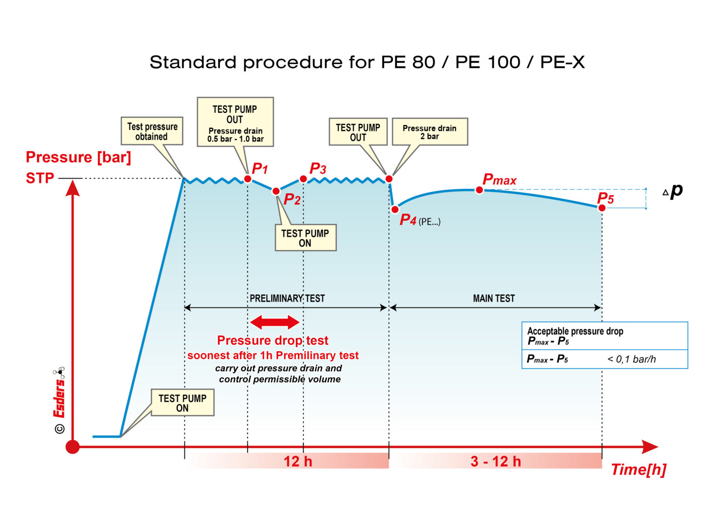
Note on plastic pipes (PE 80, PE 100, PE-X)
In addition to the previous version of DVGW worksheet W400-2, when performing the main test, it should be noted that, as a result of the pressure drop in the test pressure by 2 bar, plastic elastic deformation of the plastic pipe occurs, so that, as with the contraction test, an increase of pressure can be observed.
For PE 80, PE 100 and PE-X, the standard procedure is used in modified manner. At the start of the main test, the pressure is quickly reduced by 2 bar. Afterwards the main test runs and the pressure difference between the maximum during the main test and the final pressure is measured. The pressure difference must be less than 0.1 bar per hour.
Standard Procedure on plastic pipes (PE 80, PE 100, PE-X)
Do you need advice?
You have now gained a deeper insight into the various procedures of water pressure testing according to W 400-2. It is clear that this task requires a lot of technical know-how and precision. At Esders, we pride ourselves on having this expertise and making it available to our customers. We are ready to assist you with your pressure measurement challenges and ensure that your systems meet the highest standards.
Don’t hesitate to contact our technicians to learn more about our products. We will get back to you in a timely manner!